
Ecliptic Engines: Compact, Efficient, and Powerful
Next Generation Propulsion Technology
Ecliptic Engines is redefining internal combustion by eliminating the mechanical limitations of traditional reciprocating pistons. Our propulsion philosophy is built around continuously rotating, intermeshing geometries that eliminate heavy reciprocating mass, optimize thermodynamic efficiency, and maximize power density.
Designed for automotive, marine, aviation, and industrial applications, the set about extracting more useful work from less fuel. The prototype programme specifically measures efficiency, emissions, combustion stability and power.
Our architectural portfolio features two distinct, ground-breaking rotary concepts:
The Integate Core supercharged diesel engine, and the Intermesh Core petrol engine.
The Integate Core: Purpose-designed for compression-ignition and advanced lean-burn applications, the Integate Core integrates a mechanically controlled gateway, allowing the expansion cycle to outlast the cavity/housing alignment. Featuring a fuel-lubricated sealing matrix, ECU-controlled iEGR management, it is designed for extreme efficiency, sustained continuous torque, and rugged thermal management.
Core Operating Principle
- Forced-Air Reloading: A positive-displacement supercharger delivers low-level boost (1.2 bar absolute / 2.9 psi gauge) to clear spent gases and reliably reload the combustion chamber.
- Compression Sequence: Trapped air is pushed into the cavity by the convex leading lobe surface. Small grooves in the circular housing walls form a passage for air to flow into the approaching cavity, flushing out remaining exhaust gases before the mixture is compressed to approximately 20:1. The airflow channels in the housing only open when the rear-facing tip of the cavity arm rotates clear of the other end.
- Compression Ignition: Fuel is injected and compression ignition occurs as the lobe reaches the rear of the cavity. The resulting combustion pressure is contained by the rotating sealing surfaces and produces rotational energy as gases expand into the increasing volume behind the lobe.
- expansion ratio approximately 1:25. This asymmetric compression/expansion relationship allows the combustion gases to continue doing useful work long after conventional cycles would have exhausted.
Advanced Sealing Architecture & Seal Hand-off
The Integate Core implements a highly precise sealing paradigm based on a core engineering principle: mechanical geometry provides the seal, combustion pressure assists the seal, and a diesel film supports lubrication and microscopic sealing.
Rotors and Articulated Sealing Segments
The cavity rotor incoporates three hinged segments and the lobe rotor incorporates four hinged segments. Each segment is spring-loaded towards the housing and closely counterbalanced to minimize centrifugal loading and unnecessary friction at elevated rotational speeds. The articulated geometry allows these sealing sections to continuously alter their positions as they transition through the cavity, housing, and overlapping regions. Crucially, combustion pressure is directed to act behind the sealing components, physically assisting in holding them securely against the required sealing surface.
The Controlled Seal Hand-off & Intermeshing Sequence
During rotation, the chamber seal and kinematic transition are continuously transferred between the leading/trailing lobe sections and the cavity arms via a precise, continuous mechanical progression:
- Retraction & Wall Tracking: As a leading seal segment moves through the cavity, direct interaction with the cavity arm physically pushes it into its most retracted position, preparing it for transfer to the housing. Concurrently, the cavity arm rides firmly against its designated section of the chamber wall.
- Overlap Entry & Exhaust Sealing: This tracking continues smoothly as the cavity arm tip enters the overlapping area, where interaction with the trailing lobe segment begins. The leading lobe tip maintains absolute chamber sealing until it completely passes the exhaust port.
- Transition & Float: Beyond the exhaust port, the circular housing gradually increases in diameter. As the leading lobe moves onto this widening section, it smoothly reaches the limit of its travel and floats close to the enlarged housing portion, no longer required to maintain chamber sealing because the trailing seal takes over.
- Arm-to-Lobe Sweeping: Next, the trailing lobe segment moves directly onto the cavity arm as it rotates past the housing. The cavity arm tip continuously sweeps across the lobe segment until it smoothly transitions all the way onto the lobe barrel.
- Gateway Creation via Cam Profile: At this point, the gear ratio dictates that the arm and the barrel rotate at exactly the same speed. The profile of the lobe barrel shape is intentionally designed to be non-concentric to the lobe center; it is specifically shaped to push the cavity arm inward toward its axis. This mechanical inward displacement is what holds the forward-facing tip clear from the cavity housing ahead, creating the internal expansion gateway that allows expanding gases to continue to exit the cavity increasing the volume pushing on the lobe.
- Gateway Closing & Cycle Reset: After a calculated period where this barrel section remains concentric to sustain the gateway opening, the barrel profile reduces in size. This reduction closes the gateway and seamlessly delivers the leading lobe tip back onto the housing wall in time to separate the next combustion area from the exhausting event of the expanded chamber.
Integrated Diesel Lubrication System
The Integate Core utilises diesel fuel as the primary lubricant for all sliding components:
- Metered Internal Galleries: Internal diesel galleries inside the lobe rotor are supplied through the rear end wall. Connecting channels precisely meter fuel through periodic alignment during rotation. To prevent stationary chamber flooding, the engine stops at a predetermined position where these passages do not align.
- Automatic Distribution: Moving lobe segments cyclicaly uncover internal channels to wet the rotor body where the lobe protrudes. The rearward-facing tip of a cavity arm acts as a mechanical squeegee, collecting and spreading the diesel across the convex leading lobe surface, which is subsequently transferred onto the lobe tip and adjacent housing wall. Additional diesel exits where the convex trailing lobe segment meets the rotor body. As the next forward-facing cavity tip enters this wetted area, the rolling/intermeshing movement distributes fuel across the cavity arm and lobe rotor barrel. The cavity arm then contacts and lubricates the circular housing wall, carrying a small quantity forward for the next sweeping interaction.
- Chamber End Lubrication: The lubricating channels of the four lobe rotor segment seals are open at each end to the chamber end walls. Movement of the lobes and cavity rotor arms spreads the diesel across the chamber end surfaces, providing controlled lubrication across the entire axial interface.
Safety Clearance and Transient Leakage Gaps
To prevent physical rotor-to-rotor collisions, the interacting geometry maintains a very small, strictly controlled safety clearance. At certain transient points in the rotation, a sealing tip may experience only a small contact area or point contact with the opposing surface, creating a potential transient gas-leakage path. The design minimizes this clearance to the absolute threshold of mechanical safety, utilizing a thin diesel film to bridge microscopic surface irregularities and assist with sealing during these brief transition windows.
End-Wall Sealing Development Options
To prevent lateral gas escape and manage high-speed dynamic movements, manufacturing tolerances, thermal expansion, and housing distortion, the design features a multi-layered end-sealing matrix:
- Temperature-Controlled Clearance: The design exploits a deliberate mismatch of expansion rates, pairing steel rotors with an alloy housing. Because the alloy housing expands faster, liquid-cooling the housing allows regulated dynamic housing contraction to shrink it to the rotor width and maintain tight, mathematically optimal operating clearances.
- Floating Ceramic End Pieces: Associated with the articulated rotor segments, these floating end pieces are made from Silicon Nitride (Si₃N₄) to reduce the moving mass of the components. Rather than relying on a fixed end-wall clearance, they are lightly spring-loaded toward the housing end walls. This allows them to float and maintain a controlled running interface that naturally accommodates housing distortion and dynamic movement.
- Dual Labyrinth Joints: A labyrinth joint can be incorporated between the floating ceramic end piece and the main segment body at each end of the segment, providing two independent leakage-restriction systems. Utilizing alternating crowns and pockets, any escaping gas encounters a tortuous sequence of restrictions and expansion pockets, drastically reducing the effective leakage path when sealing surface contact is minimal.
- Diesel-Wetted Labyrinth Interfaces: A very thin diesel film is managed within the labyrinth system. This film is not intended to flood the labyrinth, but rather to lubricate moving interfaces, provide boundary lubrication during transient contact, reduce wear, and occupy part of the microscopic gas-flow clearance to provide additional leakage resistance.
Advanced Combustion & Emissions Control
Internal Exhaust Gas Recirculation (iEGR)
The Integate Core integrates an internal Exhaust Gas Recirculation (iEGR) system actively managed via a dynamically modulated control valve built directly into the housing port and governed by the engine’s ECU, to precisely meter, target, and trap a calculated mass fraction of residual exhaust gas. This closed-loop control dilutes the intake charge to flatten peak flame temperatures, and reduce fuel requirements and pollutants.
Possible Spark-Assisted Compression Ignition (SACI) Integration
To expand the engine’s operational envelope and fuel flexibility, the architecture is designed to accommodate a Spark-Assisted Compression Ignition (SACI) development path.
- Flame-Kernel Control: In SACI mode, a spark plug initiates a localized flame kernel within a lean or heavily iEGR-diluted mixture.
- Pressure-Driven Compression Ignition: The thermal expansion of this initial spark-ignited flame raises the pressure and temperature inside the remaining unburned zone of the cavity, triggering a highly controlled, phased compression ignition.
- Combustion Stability: By using the spark timing as an active trigger, SACI resolves the historical cyclic variability and timing control issues inherent to pure compression ignition under high EGR dilution, allowing for smooth, ultra-efficient part-load operations.
Dynamic Thermal Management
The Integate Core operates in an asymmetric thermal environment, with combustion and intake regions experiencing vastly different conditions, the effects can be potentially be reduced using Thermal Barrier Coatings : Non-contacting, combustion-facing areas are treated with selective coatings like Yttria-Stabilized Zirconia (YSZ). This reduces heat transfer into the rotor, prevents severe thermal gradients and distortion, and retains more combustion energy within the gas.
Geometric Reference Specifications
- Compression Ratio: ~ 20:1
- Maximum Expansion Ratio: ~ 1:25
- Combustion Events: 3 per cavity-rotor revolution
- Power Stroke Duration: ~ 142° per combustion event (426° combined total per revolution)
- Volume Per Combustion Event: ~ 485.7 cc
- Geometric Working Volume: ~ 1,457 cc (1.45 Litres) per rotor revolution
- Max Geometric Expansion Volume: ~ 600.5 cc (for one cavity at 94.5 mm depth)
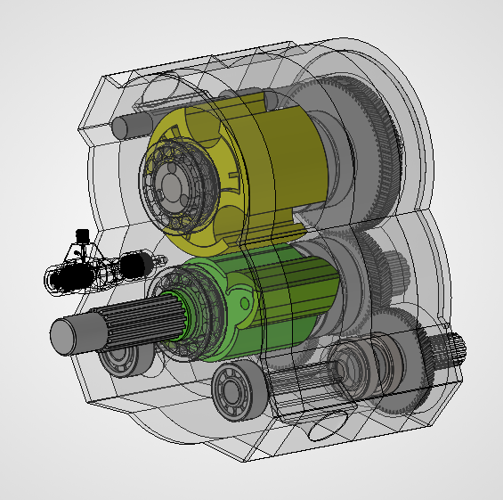
- Weight at the stage shown: 40 kg
- Equivalent Inducted Charge: ~ 1.75 Litres per revolution at 1.2 bar
Designed around standard catalogue Helical gears for robust mechanical synchronization, the design is scalable to a back-to-back configuration designated the Double Integate Core.
The Integate Double Core consists of two independent Single Core combustion chambers configured back-to-back, separated by the central gearing system. While the Single Core is the preferred starting point for engineering validation of the sealing, lubrication, combustion, thermal, and dynamic systems, the Double Core maps the ultimate commercial potential of this architecture.
With identical geometry, the Double Core provides twice the number of combustion events—6 combustion events per rotor revolution—providing substantially greater continuous torque production and power density within a highly compact architecture.
Key Engineering Development Areas & Philosophy
The immediate development philosophy follows a staged process targeting experimental verification over simultaneous optimization: Engineering → Prototype → Measured Performance → Validated Technology → Licensing.
The next engineering stage focuses on validating the precise mechanisms determining core performance and durability:
- Combustion & Gas Flow: Validating 20:1 compression ignition and SACI transition boundaries, fuel injection timing, active ECU-governed iEGR port valve mapping, gateway flow dynamics, and safety clearance leakage rates.
- Rotor Dynamics & Tribology: Assessing articulated segment movement, hinge loads, counterbalancing, high-RPM behaviour, and diesel lubrication retention.
Thermal & Materials: Mapping housing/rotor growth, optimizing the temperature-controlled clearance strategy, and analyzing the ceramic/metal interfaces of the Silicon Nitride components and YSZ coatings.
The Intermesh Core: The rotary architecture utilises a two-lobe fast rotor meshing with a three-cavity slow rotor. Designed for extreme high-RPM, vibration-free power delivery, it features a broad torque curve, integrated Exhaust Gas Recirculation (EGR), Spark assisted compression ignition for a clean burn and an asymmetric expansion cycle tailored for high power density.
The Intermesh Single Core
At the heart of the platform is the patent-pending Intermesh Core, consisting of a two-lobe fast rotor meshing with a three-cavity slow rotor. Unlike conventional piston engines, the components don’t reciprocate, greatly reducing friction, vibration, and mechanical losses.
Each slow-shaft revolution produces three evenly spaced combustion events, with a power stroke every 120° of rotation. Every combustion event delivers approximately 60° of continuous torque, producing a broad, flat torque curve while maintaining smooth operation without reciprocating masses or offset shafts.
The engine also uses an asymmetric expansion cycle, allowing combustion gases to expand further with greater energy extraction before exhaust. This extracts more useful work from each combustion event, improving fuel efficiency while reducing exhaust heat.
A key enabling technology is the Active Clearance Control system. Rather than functioning solely as a cooling system, it actively regulates the engine’s internal geometry.
During operation the steel rotors naturally expand from both centrifugal force and temperature. However the alloy housing material will expand faster, proximity sensors within the chamber relay information to the engine control unit (ECU), which then continuously controls the flow a of specialised coolant through galleries within the aluminum housing. This allows the housing temperature to be adjusted through a broad temperature range, such that the running clearances remains extremely small and stable.
Maintaining this tiny clearance minimizes internal leakage while preventing contact between the rotating components and the housing. The result is extremely low mechanical wear, stable compression, and long service life without traditional rubbing seals.
Astron Aerospace’s Omega 1 running engine provides a significant industry precedent for a rotary engine using extremely tight clearances rather than conventional rotor-tip seals.
Astron demonstrates precision-clearance, seal-less rotary operation is a serious engineering direction being pursued in the industry, materially reducing the uncertainty around whether such an approach is fundamentally viable.
Air Management and Combustion
The Ecliptic Engine combines high-speed scavenging with controlled combustion to maximize efficiency.
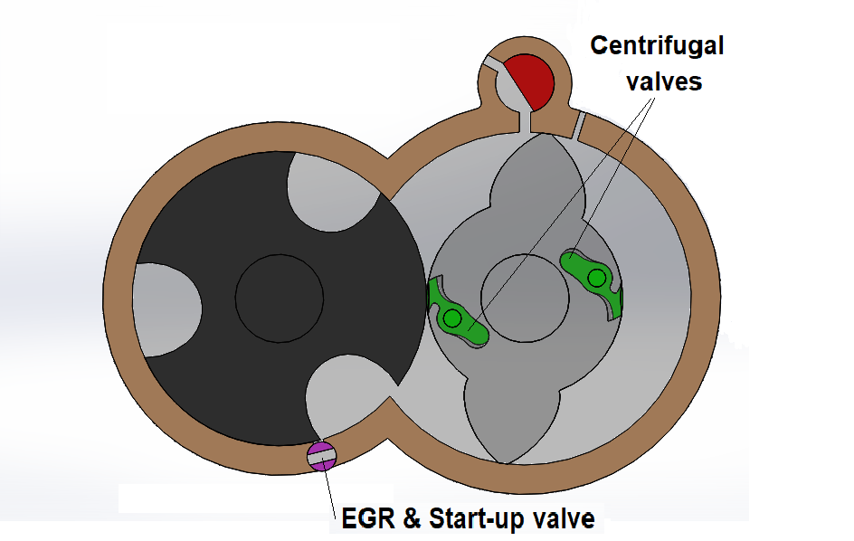
During each cycle, the lobe rotor pre-compresses a charge of air which is then used to clear the exhaust gases from the chamber spaces. Air follows two separate flow paths; the first to open is the notch pathway that allows flow between the rotors, the second pathway opens as the leading cavity edge rotates past the housing apex and into the intermeshing area. This dual-path scavenging achieves the cylinder-cleaning benefits traditionally associated with two-stroke engines while avoiding their oil consumption and emissions.
To ensure that both flow paths receive a their share of the pre-compressed air, a moderating valve (not shown in the animations) is included in either or both of; the perimeter of the cavity rotor; the barrel of the lobe rotor (as shown in the picture below,with hidden springs included). Centrifugal energy increases with RPM causing the notch valve gate to progressively open to allow more flow between the rotors to clear the chamber space ahead before the cavity gapes open and takes the remainder of the air. Alternatively the valve gates could be controlled by solenoids and the ECU.
Once the chamber is sealed, high-pressure piezoelectric injectors introduce fuel into the highly turbulent air, promoting rapid mixing before ignition.
Starting & Air-Mass Management
Conventional seal-less rotary engines can struggle to develop sufficient compression during cranking because internal clearances are intentionally larger when cold. The Ecliptic Engine addresses this through a dedicated activation mode.
At cold start, the internal EGR system and barrel notches are completely closed, and the entire operational fluid space is filled with clean air after wind-down. Because the part of the charge that usually pushes the hot gas out of the engine is combined with the air already in the engine the charging footprint captures 3 times the regular compression volume for the very first ignition event. This deliberate air accumulation offsets air escaping the chamber as rotor blow-by, through the cold assembly clearance during cranking, drastically reducing the starter motor RPM required for an instant fire. The remaining dense fresh air charge at Top Dead Center provides a powerful initial combustion wave, potentially forcing the engine past its idle threshold on the first full rotation. This feature also means the starter motor size and weight requirements are greatly reduced, making the overall Ecliptic design more viable as a transport engine.
The Ecliptic chamber geometry creates a long, narrow combustion path. Traditional spark ignition requires the flame front to travel across the depth of the chamber, resulting in poor fuel burn and unwanted emissions. To avoid that the combustion is controlled using Spark-Assisted Compression Ignition (A-SACI). This combines the efficiency of homogeneous charge compression ignition with the precise timing control of conventional spark ignition. The combustion chamber contents must be brought to a pressure level just below the auto-ignition threshold, a precisely timed spark initiates combustion in a small portion of the mixture, creating the pressure and temperature required for the remainder of the charge to auto-ignite almost simultaneously.
The engines compression ratio alone is not sufficiently dense to create the auto-ignite conditions, elevated temperature is the additional factor. The Ecliptic design has two systems to raise the temperature:
- An integrated Internal Exhaust Gas Recirculation (iEGR) system , controlled amounts of hot exhaust gas are retained within the engine to accelerate warm-up, improve combustion stability, and help establish the temperatures required for efficient compression-assisted ignition.Once at operating temperature, the ECU continuously adjusts iEGR levels alongside spark timing to maintain stable combustion while minimizing NOx formation and improving fuel efficiency across a wide operating range.
- Raising the temperature of the cavity wall. Within the Intermesh Single Core each cavity returns to duty once per rotation, maintaining the temperature in the chamber using a similar frequency to a two-stroke engine with SACI technology comes from. The dual-flanked version doubles the combustion-event frequency, creating hotter combustion, gas-management and mechanical environment.
Ecliptic Engines Intermesh Dual-Flanked Core


The dual-flanked configuration is the preferred first physical prototype because it is the smallest practical architecture that meaningfully validates the core systems needed for the eventual quad-core. The single core is useful for basic mechanism validation, but the dual-flanked version doubles the combustion-event frequency, bringing the engine into the more demanding thermal, combustion, gas-management and mechanical environment that the quad will ultimately face. It therefore allows us to test SACI, iEGR, charge transfer, clearances, leakage, bearings, gears, thermal behaviour, vibration, mechanical losses and power in a configuration that is directly relevant to the final architecture.
Theoretical Case study R67 Intermesh Dual-Flanked Core: The design above shows a weight of 60kg in the CAD program mass calculation. There is trimming that can be done to reduce the weight, and there are peripheral components to add that will increase it, but it gives a reasonable figure to work with. The estimated power output after parasitic losses at 10,000 RPM is approximately 170. HP. If the all rotary design incorporates high grade bearings, lubricants, and protective coatings on the internal parts, then it is theoretically capable of much higher rpm such as 15000 RPM, which would deliver around 250 HP.
The dual-flanked module is the fundamental building block of the intended quad-core: once its behaviour is measured and validated, two validated modules can be combined into the quad rather than having to redesign the engine after proving a single-core concept.
Intermesh Quad Core
Two dual-flanked chambers mounted back-to-back around a central gear bank as a single synchronized assembly. Twelve combustion events per output revolution, delivering exceptionally smooth, continuous torque.


Theoretical Case Study: Intermesh Quad Core R67. Using the CAD design program mass feature shows 102kg at the development level shown. At 10,000 RPM the output indication is 340 HP, and the 15,000 RPM is 500HP. In this scenario the fast shaft is doing 22500 RPM.
Manufacturing
The engine has been designed for economical high-volume production using established manufacturing methods.
- Sintered copper-steel rotors with hardened wear surfaces.
- Aluminum housing incorporating liquid cooling galleries.
- Hardened steel drive splines and precision herringbone timing gears.
Commercial Opportunity
The fastest path to a return is through the licensing of the engine designs. Technology transfer fees, and a royalty per unit would be payable. An existing engine manufacturer with existing production capacity would likely find great value in the production and distribution rights. The simplified architecture uses substantially fewer components than conventional piston engines, reducing machining, assembly time, manufacturing cost, and overall weight. The result is a more desirable engine that costs less to manufacture, that can be sold through their existing channels at a more profitable rate, making the royalty arrangement favourable for both parties.
IP Protection: The core Intermesh architecture has progressed through the New Zealand patent process, and has been accepted by the Patent Examiner, and granting is expected at the beginning of November. National-phase protection already planned in: United States • Canada • Australia • New Zealand
Ecliptic is currently assessing additional jurisdictions where this patent should be pursued to maximise future licensing territory. Capital raised now can be used to secure the commercially important additional territories before the national-phase opportunity closes. International patent filings are scheduled before the 31 month deadline on September 29 2026 . A more recent second provisional patent covers the directional airflow moderating valves.
The impending deadline is reason that this opportunity is freshly uploaded and here for you to consider today. The company is offering equity in return, or will consider an alternative commercial partnership to support prototype development and commercialization.
Development Strategy
Initial funding target: NZ$25,000 This urgent investment is to secure IP protection in the most affordable and viable jurisdictions.
Second Funding Target: NZ$50,000- $75,000 This investment will take Ecliptic from its current patented/CAD stage to a build-ready, engineered and independently reviewed dual-flanked prototype programme. The funding is directed towards: , completing the dual-flanked design, gas-exchange and variable-notch modelling, centrifugal-gate analysis, SACI investigation, mechanical-load analysis, independent engineering review, prototype drawings, manufacturing quotations.
Next prototype round: NZ$150,000–$200,000
Once the engineering package and manufacturing quotations are complete, the larger round funds the manufacturing and instrumentation of the dual-flanked engine, and the actual testing required to establish its operating envelope — including RPM, torque, vibration, temperature, sealing, lubrication, gear/shaft loading, pressure, charge transfer, EGR, combustion, SACI stability, fuel consumption and emissions.
The investment proposition is all about removing technical uncertainty and protecting the IP:
IP → engineering → prototype → measured performance → validated module → strategic licensing.
Please get in touch for more info and to let me know how you can help, and what you’d like in return.